 |
|
|
Contact: lily at cs.caltech.edu Acknowledgments: This is a joint project with Boris Springborn and Peter Schröder. This work was supported in part by NSF (DMS-0220905, DMS-0138458, ACI-0219979), DFG Research Center MATHEON "Mathematics for Key Technologies", DOE (W-7405-ENG-48/B341492), Center for the Mathematics of Information, Alias, and Pixar. Special thanks to Alexander Bobenko, Mathieu Desbrun, Nathan Litke, Ilja Friedel, Cici Koenig, Matthew Fisher, Manuel Lombardini, and Donnie Pinkston. |
![]()
This code is an implementation of the Circle Pattern method for finding discrete conformal Delaunay
parameterizations of triangle meshes of arbitrary genus. In short, this method works as follows: given the initial mesh (and values for the cone singularities
in case of higher genus meshes) it computes an optimal arrangement of circumcircles of the faces of the mesh. This arrangement is found in two steps,
first quadratic programming is used to find the angles under which the circles intersect,
than non-linear minimization is used to find the radii of the circles. Intersection angles and radii of the circumcircles give enough information to
compute lengths of the edges in the mesh, which determines the final layout of the parameterization.
To parameterize higher genus meshes one can use cone singularities at designated vertices and a valid set of cuts to develop the surface.
The parameter domain is then a piecewise flat surface. Cone singularities can also help to reduce the often very large area
distortion of global conformal maps to moderate levels. The current version of the code can take input cone singularities and output
the edge lengths of the new parameterization. Alternatively, it can take as an input cone singularities and a valid set of cuts,
and produce parameterization patches that have a boundary over the given cuts.
![]()
The code can be used with Windows or UNIX operating systems. The only external library used is MOSEK (which is free for students).
This library does numerical optimization, in our case quadratic programming and non-linear convex minimization. If you can download this library for your operating system
and link it to the CirclePatterns code, you should have no problem running the code on different operating systems. We provide a Visual Studio .NET project for Windows and
sample makefile for UNIX. Make sure that the path for the MOSEK library and include files corresponds to those on your computer.
![]()
After the application is compiled either using Visual Studio or the Makefile, it can be called with command line arguments to compute parameterizations of triangle meshes.
Standard way to call the application is:
CirclePatterns.exe <INPUT_OPTIONS> <OUTPUT_OPTIONS> [OTHER OPTIONS] | <TEXT_FILE_WITH_OPTIONS>
Where the supported options are:
- -io <input obj file>
Give the path for the input OBJ file that needs to be parameterized. - -oo <output obj file>
Give the path for the output OBJ file; computed parameterization is stored in vt coordinates of that file. - -ic <input CON file>
Give the path for the input CON file that needs to be parameterized, see below for the information on CON format. - -iv <singularities file>
Give the path for the input file with cone singularities; see below for the information on the format. - -ie <edges to cut file>
Give the path for the input file list of edges to cut; see below for the information on the format. - -oc <output CON file>
Give the path for the output CON file; computed parameterization is stored as new edge lengths. - -ovt <otput vt file>
Output only vt coordinates, in the same ordering as original vertices - -no
Only cut (if cuts are provided) and layout mesh, no parameterization is computed. Input mesh needs to be a piecewise flat surface. - -help
Outputs usage message. - <text file with options>
All the options from above can be stored in the text file and then the text file is passed to the program as a single command line argument.
Check files with options and other input files in the sample input to learn more about options and formats. Sample input shows few examples of how to do parameterizations with natural boundary, fixed boundary, cone singularities, and cuts.
![]()
OBJ format:
Standard obj format is used to represent triangle meshes. If the mesh does not have texture coordinates,
the OBJ file is just a list of lines that start with 'v' and are followed by 3 doubles to represent vertex positions and a list
of lines that start with 'f' and are followed by three integers to represent vertices of each face:
v <x_coord>
<y_coord> <z_coord>
v <x_coord> <y_coord> <z_coord>
.
.
f <vert_id_1> <vert_id_2> <vert_id_3>
f <vert_id_1> <vert_id_2> <vert_id_3>
.
.
Note: vertex ids go from 1 to N, where N is the number of vertices in the mesh.
When texture coordinates are assigned, the format changes to the following:
v <x_coord> <y_coord> <z_coord>
v <x_coord> <y_coord> <z_coord>
.
.
vt <x_uv_coord> <y_uv_coord>
vt <x_uv_coord> <y_uv_coord>
.
.
f <vert_id_1>/<vert_uv_id_1> <vert_id_2>/<vert_uv_id_2> <vert_id_3>/<vert_uv_id_3>
f <vert_id_1>/<vert_uv_id_1> <vert_id_2>/<vert_uv_id_2> <vert_id_3>/<vert_uv_id_3>
.
.
CON format:
In order to represent mesh connectivity with edge length for each edge, we changed OBJ format to store that information. Note that only edge lengths are known, not the position of the vertices. The lines in the CON file are as following:
<number_of_vertices>
<number_of_faces>
f <vert_id_1> <vert_id_2> <vert_id_3>
<edge_length_1> <edge_length_2> <edge_length_3>
f <vert_id_1> <vert_id_2> <vert_id_3>
<edge_length_1> <edge_length_2> <edge_length_3>
.
.
Warning:This format has some drawbacks: only regular meshes can be represented, only triangle meshes are parsed easily. It might need to be improved later, when the method is extended.
Note: vertex ids go from 1 to N, where N is the number of vertices in the mesh.
Cone Singularities file format:
This file is used to give information about allowed cone singularities in the parameterization. In order to learn more about cone singularities refer to Section 4 in the paper.
The input file is a list of lines:
<vert_id> <min_angle> <max_angle>
Note: vertex ids go from 1 to N, where N is the number of vertices in the mesh.
The values for the angles are given as multiples of pi, e.g. 0.5 means 1.57.. radians. Maximum and minimum values for the cone angle can be (and usually are) the same.
Edge Cuts file format:
This file gives information about cuts provided by the user. Format of the file is a list of lines:
<
vert_from_id> <vert_to_id> <face_id>
The information in the file is somewhat redundant, but as eventually we want to allow non-regular meshes, there might be two half edges with the same end points.
Note: vertex ids go from 1 to N, where N is the number of vertices in the mesh; face ids go from 1 to M, where M is the number of faces.
![]()
Mesh:
The input meshes need to be 2-manifold connected regular triangle surfaces stored in either OBJ or CON format. Although this method can be used to parameterize some non-regular surfaces,
the current version of the code does not support this. If the mesh has holes, they need to be filled prior to parameterization.
When no cone singularities are defined, only genus zero meshes with a single boundary can be parameterized,
see requirements for cone singularities and edge cuts to learn more about parameterization of higer genus meshes.
Because the resulting parameterizations are Delaunay, conformal distortion is minimized then input meshes are also intrinsically Delaunay. The simplest way to do this is to perform a series of edge flips whenever there are edges that do not satisfy the Delaunay property: the sum of two angles opposite to an edge is greater than Pi. To lower the error the mesh can be transformed into an Intrinsic Delaunay Triangulation ([2] and Section 5 of the [3]), and given as input in CON format (in few cases the result of the Intrinsic Delaunay Triangulation algorithm is a non-regular mesh, current version of the code needs to be extended to handle those cases). Then the result can be output in CON format and all the edges that were flipped can be flipped back to achieve original triangulation. In the future we will try to provide additional code to do this. Of course, non-Delaunay meshes can also be parameterized, but the angle distortion may be higher in that case.
Cone Singularities:
The main requirement for input cone singularities in the file is for the cone angle divided by pi to be in (0, valence_of_vertex) range, which means the actual cone
angle is bounded by 0 and pi*(valence of the vertex) or equivalently Gaussian curvature of the singularity vertex is between pi*(2 - valence of the vertex) and 2*pi.
The cone angle at a vertex is defined as the sum of incident angles and the Gaussian curvature at a vertex is 2*pi minus the cone angle.
After all the singularities are prescribed, the Gauss-Bonet Equation:
![]()
where Kappa_i is the Gaussian curvature at interior singularities, and kappa_i is the curvature at the boundary vertices
(curvature at the boundary is equal to pi minus the sum of incident angles at the boundary). In order to be sure that the equation
is satisfied, it could be useful to give a range as a value for the cone angle of a singularity.
Giving a range, especially a large range for all singularities, usually does not give the best results in terms of area distortion.
Edge Cuts:
When the mesh is parameterized with cone singularities, it needs to be cut in order to assign texture coordinates for all the
vertices. The best way to understand why cuts are needed is to imagine a paper cone, which needs to have at least one cut from the tip
to the boundary of the cone to lay it flat on the table, or a rubber torus, which needs to have two cuts to stretch the rubber over the table.
In our case cuts have exactly the same purpose: they need to transform higher genus surfaces into the topological disk and allow singularities
to be developed into the Euclidian plane. So the cuts need to be assigned in such a way that all the cone vertices have at least one cut
touching them, and after the mesh is cut, all the components are topologically equivalent to a disk. It is also possible to save the resulting
parameterization in the CON format, and cut it later, when the texture coordinates are needed. The other option is to save the mesh in CON format
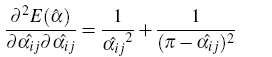
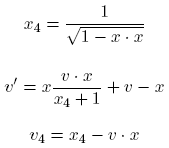
and find texture coordinates only for the parts of the mesh which need to be textured (see Feline figure).
![]()
This code is only an example of how the circle pattern method can be used. The code can be used either as a separate application
for finding a parameterization of the mesh or as a guideline on how to implement the circle pattern method for parameterizations.
One can write utility programs that generate cone singularities that minimize area distortion of parameterizations;
or compute cuts that are optimal for packing parameterized patched in the texture plane; or create parameterizations over the
sphere or unit disk or other 2D domains; etc.
The code is also structured in such a way that it should not be too difficult to adapt it for a different nonlinear solver.
Refer to the documentation in the AnglesOptimization,
CirclePattern, and
EnergyMinimization classes for more information.
![]()
Currently the "black box" external library MOSEK is used to perform quadratic programming
for finding optimal theta angles and convex unconstrained non-linear minimization for finding the radii of the circumcircles
of the triangles in the parameterization. One could use a different non-linear solvers if either one does not have access to
MOSEK or a better solver is available. This will require some changes in the code, however as most solvers
use a similar interface, the changes will be minimal.
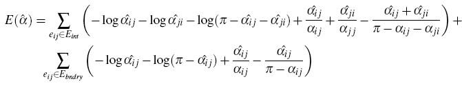
If you do not have a library to do quadratic programming, the problem of finding optimal theta angles can be rewritten as convex non-linear minimization with linear constraints. We found that the results of such a minimization are similar to those of quadratic programming. The non-linear problem has the following set up:
Energy:
(let alpha ij and alpha ji be alpha angles opposite to the edge ij; all the alpha hat angles are the variables – the angles we are looking for, and alpha (without hat) are the correspondent angles in the
original mesh).
Gradient:
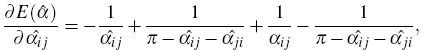 |
for angles opposite to internal edge. |
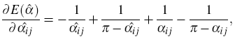 |
for angles opposite to boundary edge. |
Hessian:
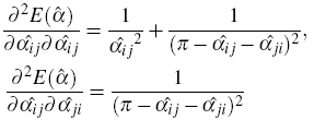 |
for angles opposite to internal edge. |
 |
for angles opposite to boundary edge. |
In cases when division by zero occurs, infinity (some very large number) needs to be returned.
Constraints:
There are two types of linear constraints for alpha angles:
- all alpha angles inside a triangle sum to pi;
- all alpha angles around a vertex sum to the prescribed cone angle of the vertex.
![]()
It can be useful sometimes to parameterize closed genus zero mesh onto the sphere.
The algorithm to do it is: remove one vertex of the mesh and all incident faces; use CirclePatterns code to do
the parameterization into the plane; apply stereographic projection to the result and add the missing vertex at
the north pole. Then, in order to get lower area distortion, normalization on the sphere can be performed.
One way to do the normalization is to put the barycenter of all the vertices at the center of the sphere.
There is a unique Lorentz transformation which achieves this, as shown in [4]. In order to do this normalization, first find x,
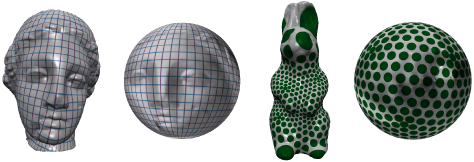
which is a minimum of the following energy (v are the coordinates of all the vertices on the sphere):
| Energy: | 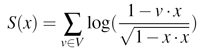 |
| Gradient: | 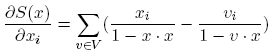 |
| Hessian: | 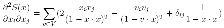 |
Then compute the Lorentz transformation which moves x to the center of the sphere. Now apply this transformation to all the vertices v.
This can be done by representing x and v in homogenous coordinates, with x4 and v4 being the 4th coordinate.
The final formula for transformation is:
As a final step, normalize v' by v4.
![]()
For some applications, such as morphing, parameterizations to the unit disk could be important.
It can be done in the following way: remove one vertex at the boundary and faces incident to it; write out a cone singularities
file that fixes the cone angle for all the remaining "old" boundary vertices to pi (1 in the file) ;
use CirclePatterns code to do the parameterization; rotate texture coordinates so that the straight line of the boundary lies
on the x axis with the rest of the mesh in the upper half plane; pick a vertex that you want to be in the center of the
final parameterization (lets call it c) and do a circle inversion around that vertex:
x' = c + (x - c) * r2/(|x - c|2), where x' are new coordinates of each vertex,
x - old coordinates, and r is the circle radius, which is equal to the y coordinate of c.
Using the concept of fixing the boundary curvatures via cone singularities input, parameterizations of different shapes can be done.
![]()
There are still a few questions to answer and directions for interesting projects. Some of them are:
- Where to put cone singularities and what the cone angle value should be to achieve small area distortion while maintaining small number of singular points?
- What is the best way to texture map a piecewise flat surface?
- Application of this parameterization algorithm for remeshing.
- Finding optimal cuts.
References:
[1] BOBENKO, A. I., AND SPRINGBORN, B. A. Variational Principles for Circle Patterns and
Koebe’s Theorem. Transactions of the American Mathematical Society 356 (2004), 659–689.
[2] FISHER, M., SPRINGBORN, B., BOBENKO, A. I., AND SCHRÖDER, P. An Algorithm for
the Construction of Intrinsic Delaunay Triangulations with Applications to Digital Geometry
Processing. In Discrete Differential Geometry, E. Grinspun, M. Desbrun, and P. Schröder,
Eds., Course Notes. ACM SIGGRAPH, 2006.
[3] KHAREVYCH, L., SPRINGBORN, B., AND SCHRÖDER, P. Discrete Conformal Mappings
via Circle Patterns. ACM Transactions on Graphics (2006). To appear.
[4] SPRINGBORN, B. A unique representation of polyhedral types. Math. Z (2005).
![]()