


|
|
|
|
|
|
 |
 |
|
|
MeshEd BasicsFundamental classesThe mesh topology is determined by some top level triangles we call Faces . It is roughly: Face
{
Face* neighbor[3];
TTree* root;
}
neighbor points to each of the neighboring Faces.root points to the root of the triangle tree (TTree). A TTree is a node in the triangle tree. It is roughly as follows: TTree
{
TTree* parent;
TTree* children[4];
Vertex* vertices[3];
}
It should be obvious what parent and children point to.vertices point to the three vertices of this particular triangle. We have affectionate names for the children; we call them T0, T1, T2, and T3. The end of this page shows how these children are arranged within a parent. A Vertex contains some data about a particular vertex. It stores, among other things, the geometric positions of the vertex at different subdivision levels: Vertex
{
CVec3 val[N];
}
CVec3 is just a simple 3-d vector class. N differs for different
vertices; for example, say we have a mesh of depth M. A vertex that exists
at the top level will have its N = M, whereas a vertex that didn't exist
until 2 subdivision iterations will have its N = M - 2. Basically each
vertex has high enough N to store all of its positions.
A Mesh is simply the following: Mesh
{
Faces* faces[];
Vertices vertices[];
}
A Mesh just contains all of the Faces in the structure, as well
as pointers to all the level 0 vertices.
Template structureThe simplicity of the class descriptions above is greatly exaggerated. All these classes are defined as templates. A typical definition looks like (take Face as an example):template<..., class FaceIf, ...>
class FaceTp: public FaceIf, ...
{
...
};
Essentially, the classes derive from their template parameters.
Since typically these classes depend on the exact definitions of
multiple other classes, this gives us a good way maintaining
strong type checking while letting us freely add data/method members
of each of the related classes.
Layers:RapidApp-> Inventor -> Geometry layer (subdivision stuff) -> Data Structure Layer ( mesh.cpp ttree face vertex vertind vring tfetcher triind names.h)  Files:
Naming Conventions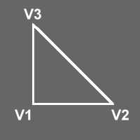 Note that orientation is not implied in the vertex naming - see last diagram. 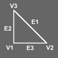 Edges are named for their opposite vertex. 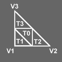 Sub-triangles are named according to their nearest vertex, with T0 in the center 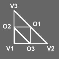 Sub-vertices are named for their opposite vertex. 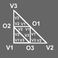 The vertex numbers of the subtriangles are the same as the nearest vertex or sub-vertex of the parent triangle. |
|
Copyright © 1998 Peter Schröder Last modified: Tue Mar 3 17:17:13 PST 1998 |